
This work package includes crucial activities of the project in terms of methodologies and materials development.
Test structures
To design the initial surface structure, a detailed literature review was carried out focusing on vortex generation and heat transfer enhancement [1, 2, 3, 4]. The surface structure introduces mixing in the thermal boundary layer and thereby increases the heat transfer by forced convection. However, increased roughness increases the flow resistance and thus the required pumping power, which is an important design parameter to be minimized. Li et al. [1] reported that the best heat transfer enhancement for a given pumping power is reached when the structure height is about three times the viscous sublayer thickness. Mondal et al. [2] offered a good reference for vortex generator geometries in BMTS as the examined flow passage geometries are similar to ours. Wu and Tao reported that [3] the optimum angle of attack of 45⁰ for the vortex generators. Esmaeilzadeh et al. [4] compared simple, curved and trapezoidal vortex generators and show that curved vortex generators have a lower flow resistance.
Based on the results reported in the literature eleven different surface structures were developed (Figure 1). The protruded rectangular vortex generators with 30⁰, 45⁰ and 60⁰ angle of attack (see fig. 1(a to c)) were adapted from Ebrahimi’s work [5]. The indented design of rectangular vortex generators with an angle of attack of 30⁰, 45⁰ and 60⁰, was implemented considering the approach of Stroock et al. [6]. The optimum angle of attack was found at 45⁰ and corroborated with [3] and [7], and was considered for surface structure shape with indented and protruded curved vortex generators (see fig. 1d) ) and protruded triangular vortex generators (see fig. 1e). The idea to use protrusions and indentations perpendicular to the flow direction stems from the paper of Li et al. [1] (see fig. 1f). While these and similar structures have been extensively studied in the context of heat transfer, their behaviour in combination with non-Newtonian coolants is largely unexplored.

Figure 1: Overview of different surface structures: (a) protruded 30⁰ winglets, (b) protruded 45⁰ winglets, (c) protruded 60⁰ winglets, (d) protruded curved 45⁰ winglets, (e) protruded triangular 45⁰ winglets, (f) protruded perpendicularly to flow direction.
Numerical optimization
The reported designs of the surface structures in the literature lack extensive optimization of relevant design parameters for the best performance. Moreover, the viscoelastic properties of the coolants and their effect on the forced convective heat transfer are not addressed yet. A numerical optimization framework is being developed to provide guidelines for designing surface structures appropriate for maximizing the heat transfer performance with viscoelastic fluids.
The optimization framework is based on
1.Numerical simulation of forced convective heat transfer problem with viscoelastic fluids
2.Maximization (or minimization) of relevant objective functions for best performance (e.g. maximum heat transfer with minimum pumping power, minimum temperature non-uniformity etc.).
In brief, the coupled momentum and energy equations are solved using fluid properties described by different viscoelastic models (e.g. Giesekus [8], FENE-P [9] etc.), followed by the determination of the objective functions, modification of the geometry accordingly and iterate the process until the maximum (or minimum) value of the objective function is attained.
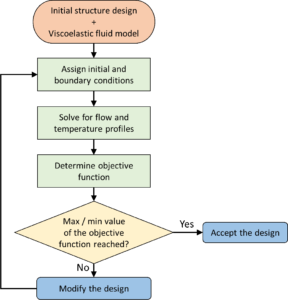
Figure 2: Flowchart of the numerical optimization framework.
Formulate the necessary SGS for the simulation of the flow and heat-transfer processes of viscoelastic media, accounting for the effects of elastic forces and shear thinning.
Main objective is to develop modelling approaches suitable for describing the rheological and thermal behaviour of the working media.
Governing equations for motion of an incompressible viscoelastic fluid including the continuity, the energy conservation and the momentum conservation equations are solved. The viscoelastic polymer stress is defined by constitutive equations defining an Oldroyd-B fluid. The set of governing equations are solved in the Finite Volume Method solver FLUENT where the viscoelastic models are implemented through the general scalar ∅ transport equation with user defined scalars (UDS).
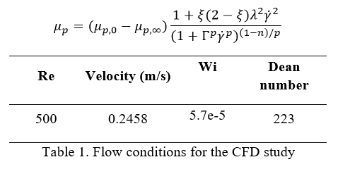
In this study, heat transfer in a bending channel is studies with three oils having different rheological properties. Three different oils used were base oil, shear thinning oil and viscoelastic oil. Table 1, describes oil properties and different constants.
Main objective is to develop modelling approaches suitable for describing the rheological and thermal behaviour of the working media.
Governing equations for motion of an incompressible viscoelastic fluid including the continuity, the energy conservation and the momentum conservation equations are solved. The viscoelastic polymer stress is defined by constitutive equations defining an Oldroyd-B fluid. The set of governing equations are solved in the Finite Volume Method solver FLUENT where the viscoelastic models are implemented through the general scalar ∅ transport equation with user defined scalars (UDS).
In this study, heat transfer in a bending channel is studies with three oils having different rheological properties. Three different oils used were base oil, shear thinning oil and viscoelastic oil. Table 2, describes oil properties and different constants.
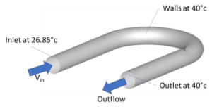
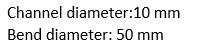
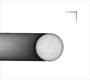
Figure 3. Computational domain, boundary conditions and cross-sectional mesh for the bending channel
For shear thinning fluids , the following relationships is used:
Referring to Figure 4. The shear-thinning fluid resembles the Newtonian fluid temperature profile, with a hot spot in the middle of the pipe. In the viscoelastic fluids as the secondary flow is supressed, the internal temperature field appears later than the other two fluids. However, after the 45° plane, it becomes visible that the thermal boundary layer thickness in the high viscosity fluid is increased and the temperature in the last slice (180°) appears to be higher than the other fluids.

Figure 4. Temperature and vorticity profiles in the channel cross sections
The average temperature evolution along the bend is presented in figure 5 for the four fluids. Viscosity of the fluid plays an important role in deciding temperature range and wall heat flux. In case of wall heat flux; lower wall heat flux for higher viscosity fluid and higher wall heat flux for lower viscosity fluid (shear thinning). And in case of temperature profile, viscosity increases the temperature of the fluid inside the channel.
Overall, the results show the role of viscosity, viscoelasticity and mixing on the temperature inside the channel. As the viscosity is reduced in the shear-thinning fluid, the wall heat flux is increased and flow mixing is more intense, resulting in a higher temperature in the channel. For the viscoelastic fluids, the polymer viscosity has an important role; the high viscosity supresses mixing but results in a thicker thermal boundary layer and therefore higher temperature in the channel. While the low viscosity, has the minimum amount of mixing compared to other fluids, which combined with a reduced wall heat flux results in the lowest temperature in the channel.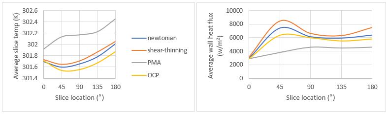
Figure 5. Average temperature in the slice (left) and wall heat flux (right) along the channel
CFD in engineering scales/benchmark geometries and liquid optimization
Main objective is to couple SGS model with CFD flow solver and validate the findings against experimental data. Simulation of the viscoelastic fluids and Nano- Fluids are carried out at engineering scale.
Phan-Thaien & Tanner (PTT) model has been implemented in a pressure-based solver and is thoroughly investigated in terms of numerical stability, numerical accuracy and convergence. The PTT model introduces 3 source terms in the momentum equations and 6 viscoelastic stress components to account for non-Newtonian fluid flow. By solving the momentum equations with the source terms and 6 more equations for the additional quantities, the evolution of viscoelastic effects is obtained.
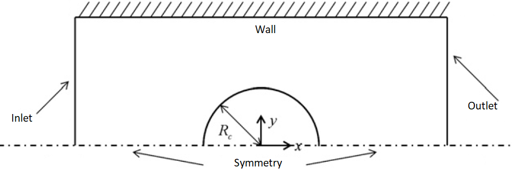
Fig. 6 Schematic of the flow configuration for the benchmark case for Non-Newtonian fluid over a cylinder Wi =0.85
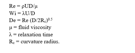
Weissenberg Number: Wi is defined as the product of the shear rate γ̇ and the relaxation time λ and is a measure of comparison of the elastic forces over the viscous forces. The domain length is equal to 30 cm and the height is equal to 2 cm. The radius of the cylinder, RC, is equal to 1 cm and the Reynolds, Re, number based on RC is equal to
Figure 7 and Figure 8 present a comparative assessment of the viscoelastic stresses S_xx and S_xy between preliminary results from the current implementation of the PTT model and the benchmark case. Qualitatively, the results of the PTT model show good agreement with the benchmark.
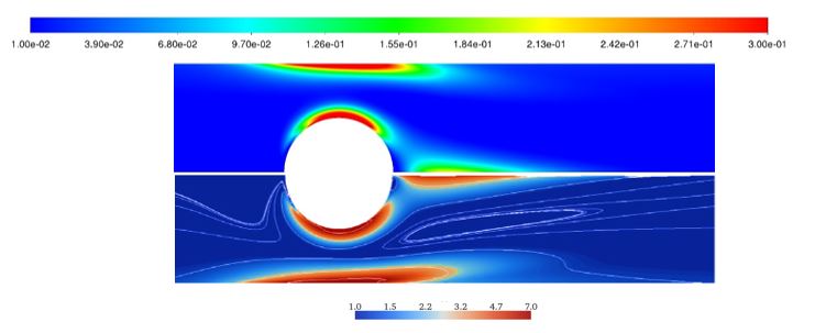
Figure 7 Comparison of shear viscoelastic stresses S_xx for flow over a cylinder at Wi = 0.85: current PTT implementation (top) and reference (bottom).
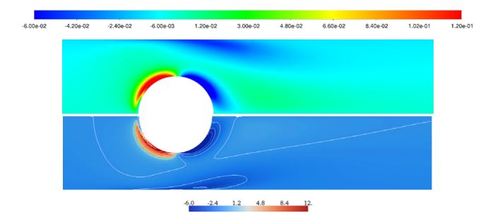
Figure 8 Comparison of shear viscoelastic stresses S_xy for flow over a cylinder at Wi = 0.85: current PTT implementation (top) and reference (bottom).
Furthermore, progress has also been made regarding numerical simulations of non-Newtonian fluids based on experimental properties provided by the project’s industrial partner (Lubrizol). The simulations incorporate non-Newtonian fluids designed by Lubrizol with specific properties to enhance heat transfer and contribute in the overall BTMS design.
References:
- X.-w. Li, J.-a. Meng and Z.-x. Li, “Roughness enhanced mechanism for turbulent convective heat transfer,” International Journal of Heat and Mass Transfer, vol. 54, p. 1775–1781, 2011.
- Mondal, C. F. Lopez, A. Verma and P. P. Mukherjee, “Vortex generators for active thermal management in lithium-ion battery systems,” International Journal of Heat and Mass Transfer, 124, p. 800–815, 2018.
- M. Wu and W. Q. Tao, “Numerical study on laminar convection heat transfer in a rectangular channel with longitudinal vortex generator. Part A: Verification of field synergy principle,” International Journal of Heat and Mass Transfer, vol. 51, p. 1179–1191, 2008.
- Esmaeilzadeh, N. Amanifard and H. M. Deylami, “Comparison of simple and curved trapezoidal longitudinal vortex generators for optimum flow characteristics and heat transfer augmentation in a heat exchanger,” Applied Thermal Engineering, 125, p. 1414–1425, 2017.
- Ebrahimi, B. Naranjani, S. Milani and F. D. Javan, “Laminar convective heat transfer of shear-thinning liquids in rectangular channels with longitudinal vortex generators,” Chemical Engineering Science, 173, p. 264–274, 2017.
- Ebrahimi, B. Naranjani, S. Milani and F. D. Javan, “Laminar convective heat transfer of shear-thinning liquids in rectangular channels with longitudinal vortex generators,” Chemical Engineering Science, 173, p. 264–274, 2017.
- Stroock, S. K. W. Dertinger, A. Ajdari, I. Mezić, H. A. Stone and G. M. Whitesides, “Chaotic mixer for microchannels,” Science, vol. 295, p. 647–651, 2002.
- Abdollahi and M. Shams, “Optimization of shape and angle of attack of winglet vortex generator in a rectangular channel for heat transfer enhancement,” Applied Thermal Engineering, 81, p. 376–387, 2015.
- Giesekus, “A simple constitutive equation for polymer fluids based on the concept of deformation-dependent tensorial mobility,” Journal of Non-Newtonian Fluid Mechanics, 11, p. 69–109, 1982.